Viti a ricircolo di sfere di alta precisione con filettatura sinistra 1605 e 4010: la scelta ideale per i moduli di guida lineare CNC.
Apr 07, 2026
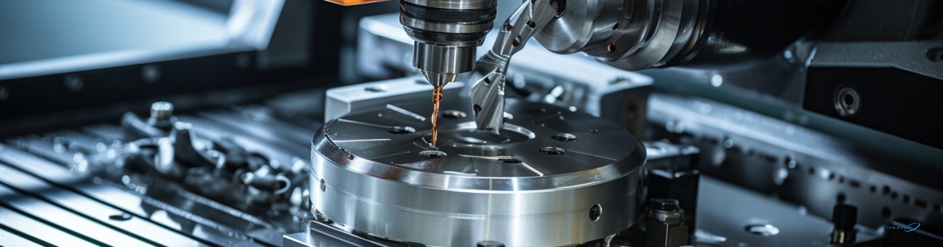
Nel campo del movimento lineare di precisione, le viti a ricircolo di sfere costituiscono il "cuore" delle apparecchiature industriali, mentre viti a ricircolo di sfere con filettatura sinistra si distinguono per le loro capacità di controllo direzionale uniche. Come produttore professionale con sede a Nanchino, Jiangsu, Cina, Shuntai è specializzata in viti a ricircolo di sfere con filettatura sinistra ad alta precisione, tra cui Modelli 1605 e 4010 con dadi a ricircolo di sfere a flangia singola, progettati specificamente per applicazioni con moduli di guida lineare CNC.Che si tratti di sviluppare macchine utensili CNC, linee di produzione automatizzate o sistemi di posizionamento di alta precisione, le nostre viti a ricircolo di sfere sinistrorse 1605/4010, abbinate a dadi flangiati singoli, offrono stabilità eccezionale, elevata rigidità e perfetta integrazione. Questo articolo approfondirà le loro caratteristiche, le applicazioni e i motivi per cui rappresentano il partner ideale per le soluzioni di movimentazione lineare.Caratteristiche principali della vite a ricircolo di sfere sinistra Shuntai 1605/4010 con dado a flangia singola1. Materiali e lavorazione di qualità superiore: acciaio per cuscinetti GCr15 per una lunga durata. Entrambi gli alberi delle viti a ricircolo di sfere 1605 e 4010 sono realizzati in Acciaio per cuscinetti GCr15 (HRC 58-62), un materiale di prima qualità rinomato per la sua elevata durezza, resistenza all'usura e resistenza alla fatica.Processi di laminazione e macinazioneOffriamo varianti sia laminate (economiche, con precisione C7) che rettificate (ultra precise, con precisione C3-C5) per soddisfare diverse esigenze di budget e precisione. Design con filettatura sinistraOttimizzato per il controllo del movimento bidirezionale, ideale per moduli CNC che richiedono posizionamento inverso o distribuzione bilanciata del carico. Dado a flangia singolaSemplifica l'installazione grazie a una struttura flangiata compatta su un solo lato, che consente un montaggio rigido su carrelli o basamenti di macchine senza necessità di alloggiamenti aggiuntivi.2. Vantaggi specifici del modello: 1605 vs 4010ParametroVite a ricircolo di sfere 1605Vite a ricircolo di sfere 4010Diametro dell'albero16 mm (misura media, salvaspazio)40 mm (diametro elevato, rigidità elevata)Guida5 mm (alta precisione, bassa velocità, adatto al microposizionamento)10 mm (alta velocità, grande spinta, ideale per il trasporto di carichi pesanti)Applicazione tipicaPiccole macchine CNC, stampanti 3D, dispositivi mediciGrandi centri di lavoro CNC, linee di produzione automatizzate, logistica per carichi pesantiGrado di precisioneC5-C7 (economico, altamente ripetibile)C7-C10 (elevata capacità di carico, stabile in condizioni estreme)3. Elevata compatibilità con i moduli di guida lineare CNCIl design del dado a flangia singola garantisce integrazione perfetta con le guide lineari, creando un sistema di movimento lineare completo: I fori passanti della flangia consentono il fissaggio diretto tramite bulloni ai carrelli delle rotaie di guida, riducendo la complessità dell'assemblaggio.La filettatura sinistra della vite a ricircolo di sfere collabora con le guide lineari per sopprimere le vibrazioni, garantendo
PER SAPERNE DI PIÙ


 Rete IPv6 supportata

 ISCRIVITI ALLA NOSTRA NEWSLETTER